Welcome to My Professional Web Portal
Connect me
 Home
Profile
Clients & Companies
Project Gallery
Contact Me
Home
Profile
Clients & Companies
Project Gallery
Contact Me


Designed By : www.easywebsolution.org
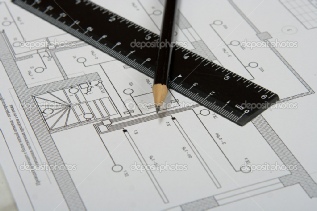
What is en Engineering Drawing?
A graphical language used by engineers and other technical personnel associated with the engineering profession. The purpose of engineering drawing is to convey graphically the ideas and information necessary for the construction or analysis of machines, structures, or systems.

Engineering drawings often include such features as various types of lines, dimensions, lettered notes, sectional views, and symbols. They may be in the form of carefully planned and checked mechanical drawings, or they may be freehand sketches. Usually a sketch precedes the mechanical drawing.
Many objects have complicated interior details which cannot be clearly shown by means
of front, top, side, or pictorial views. Section views enable the engineer or detailer
to show the interior detail in such cases. Features of section drawings are cutting-
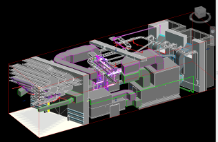
Layout drawings
Layout drawings of different types are used in different manufacturing fields for various purposes. One is the plant layout drawing, in which the outline of the building, work areas, aisles, and individual items of equipment are all drawn to scale. Another type of layout, or preliminary assembly, drawing is the design layout, which establishes the position and clearance of parts of an assembly.
Schematic drawing
Concise, graphical symbolism whereby the engineer communicates to others the functional relationship of the parts in a component and, in turn, of the components in a system. The symbols do not attempt to describe in complete detail the characteristics or physical form of the elements, but they do suggest the functional form which the ensemble of elements will take in satisfying the functional requirements of the component. They are different from a block diagram in that schematics describe more specifically the physical process by which the functional specifications of a block diagram are satisfied.
An electrical schematic is a functional schematic which defines the interrelationship of the electrical elements in a circuit, equipment, or system. The symbols describing the electrical elements are stylized, simplified, and standardized to the point of universal acceptance.
In a mechanical schematic, the graphical descriptions of elements of a mechanical system are more complex and more intimately interrelated than the symbolism of an electrical system and so the graphical characterizations are not nearly as well standardized or simplified. However, a mechanical schematic illustrates such features as components, acceleration, velocity, position force sensing, and viscous damping devices.
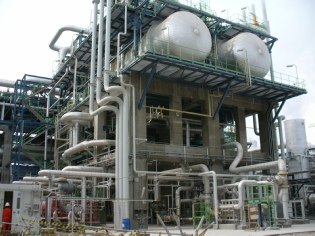
Piping
A piping "Isometric" is a three dimensional representation of a pipe line or part
of a pipe line complete with all information necessary to purchase (the material),
fabricate, install and test the line or part of the line.
In order to accomplish this
there must be certain specific information included in or on the isometric drawing. The
"isometric drawing" form is divided into sections for the required information.
These
sections are:
1. Identification (Title Block) Section
2. Technical Data Section
3. Graphic
Section
4. Bill of Material Section
The identification or title block section is
further broken down to include:
• The Line Number – The Line Number becomes the
drawing number for the isometric. The line number comes from the P&ID and the Line
List. Only part of the line number is included as the "Drawing Number" for the isometric. The
part that is used for drawing identification is only the numeric sequence number
and the Line Class specification.
• Sheet Number – When a pipe line takes more
than one sheet then there needs to be a way to identify each sheet in the Isometric
log.
• Project Number
• The name of the person creating the line/isometric
• Date
the drawing was created
• Date the Isometric is issued
• The Revision Number
• The
record of Revisions
The Technical Data section Block section is further broken down
to include:
• The Piping Code applicable to the line – from the line class specification
• The
Insulation Type – from the line list
• A designation of Shop or Field fabrication
– Design instructions
• Hydro-
• Post Weld
Heat Treat (PWHT) requirements – from the line list
• Heat tracing criteria – Type,
Temperature, etc.
The Graphic Section should include the following when applicable:
• A
North Arrow – indicating the direction of Plant North (for projects on land) or Platform
North (for projects that are Offshore Platforms). As much as possible all Isometrics
should be drawn (Plotted) with the North Arrow in the same direction. The recommended
North direction is up and to the right. Second is up and to the left.
• The
configuration – Presented in a clear and simple manner that the shop and field can
understand. This should be one line or part of one line. The key here is clear
communication from the office to the shop and the field. It is better to use two
or more sheets for a line than to try to "Save paper and crowd so much on one sheet
and end up with errors in fabrication.
• Symbology – the symbols used on each
isometric should be industry standard clear, concise and consistent no matter how
many different people draw them or what CADD system is used. Piping is a language
and the office is "talking" to the shop and the field. The communications should
not be damaged by free-
• Dimensions
– what is needed here is all the dimensions necessary to fabricate the spools shown
on the isometric. Do not include dimensions that are not necessary. Dimensions
should be given for over-
• Spool Mark Numbers – These are the identification
numbers that should be painted on the spool piece that helps the Field reassemble
the "Puzzle" of pieces.
• Notes & Callouts – Sometimes objects are required for
the line (isometric) that a simple symbol is not enough. Notes or callouts are used
to define what the object is and the size of the object. This information comes
from the design instructions.
• Reference Location Point – Every isometric need's
to have a reference location point to aid the field in location where the line is
in the big picture. If the line shown on the isometric originates (or terminates)
at a piece of equipment then the equipment number should be indicated along with
the specific nozzle designation. This is normally sufficient for location. For
isometrics that do not originate (or terminate) at a piece of equipment then one
nearby pipe support column should be indicated with its number and coordinates.
• Elevation
– at least one elevation should be given on the isometric.
The Bill-
If the BOM is on the same
paler as the isometric then include:
• The count of the material object (pipe.
fittings, flanges, etc)
• The primary size (and secondary size when applicable)
of the object
• The Item Code Number of the object – This is found in the Piping
Material Line Class Specifications.
• The Description of the object
• Comments
Box
If the BOM is a separate piece of paper from the isometric then the following
must also be included:
• The Line Number ( Isometric Number)
• The Sheet Number
• The
Project Number
• The Revision Number
• Date of Issue
Piping Isometrics (also called
Isos) are made three ways:
-
-
-
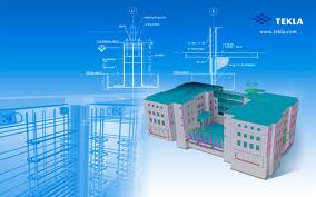
Structural Drawings
Structural drawings include design and working drawings for structures
such as building, bridges, dams, tanks, and highways. Such drawings form the basis
of legal contracts. Structural drawings embody the same principles as do other engineering
drawings, but use terminology and dimensioning techiques different from thoses shown
in previous illustrations.
Structural engineers use engineering formulas relating to material properties and physics to design structures which will withstand all the forces the structures may be subject to. Examples of such forces are gravity, wind shear, stresses due to aging of materials and seismic vibration.
Structural drawings are part of the language the same structural engineers use to communicate with contractors, fabricators and regulatory bodies. These drawings describe the details of an object's supporting members, such as beams and columns, which are designed by the structural engineer.
Structural drawings are executed by structural draftsmen. Structural draftsmen typically work under the structural engineer responsible for the structural design. Skilled structural draftsmen convert the engineer's sketches into CAD drawings, and also check that the designs conform to the relevant statutes and building codes

Civil engineering
Civil engineering is a professional engineering discipline that deals with the design,
construction, and maintenance of the physical and naturally built environment, including
works like roads, bridges, canals, dams, and buildings. Civil engineering is the
oldest engineering discipline after military engineering, and it was defined to distinguish
non-
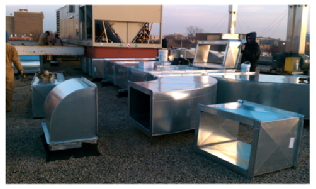
HVAC
HVAC (heating, ventilation, and air conditioning) is the technology of indoor and
automotive environmental comfort. HVAC system design is a subdiscipline of mechanical
engineering, based on the principles of thermodynamics, fluid mechanics, and heat
transfer. Refrigeration is sometimes added to the field's abbreviation as HVAC&R
or HVACR, or ventilating is dropped as in HACR (such as the designation of HACR-
HVAC is important in the design of medium to large industrial and office buildings such as skyscrapers and in marine environments such as aquariums, where safe and healthy building conditions are regulated with respect to temperature and humidity, using fresh air from outdoors.
The invention of the components of HVAC systems went hand-
The starting point in carrying out an estimate both for cooling and heating depends on the exterior climate and interior specified conditions. However before taking up the heat load calculation, it is necessary to find fresh air requirements for each area in detail, as pressurization is an important consideration.
In modern buildings the design, installation, and control systems of these functions
are integrated into one or more HVAC systems. For very small buildings, contractors
normally capacity engineer and select HVAC systems and equipment. For larger buildings,
building services designers and engineers, such as mechanical, architectural, or
building services engineers analyze, design, and specify the HVAC systems, and specialty
mechanical contractors fabricate and commission them. Building permits and code-
The HVAC industry is a worldwide enterprise, with roles including operation and maintenance, system design and construction, equipment manufacturing and sales, and in education and research. The HVAC industry was historically regulated by the manufacturers of HVAC equipment, but regulating and standards organizations such as HARDI, ASHRAE, SMACNA, ACCA, Uniform Mechanical Code, International Mechanical Code, and AMCA have been established to support the industry and encourage high standards and achievement.